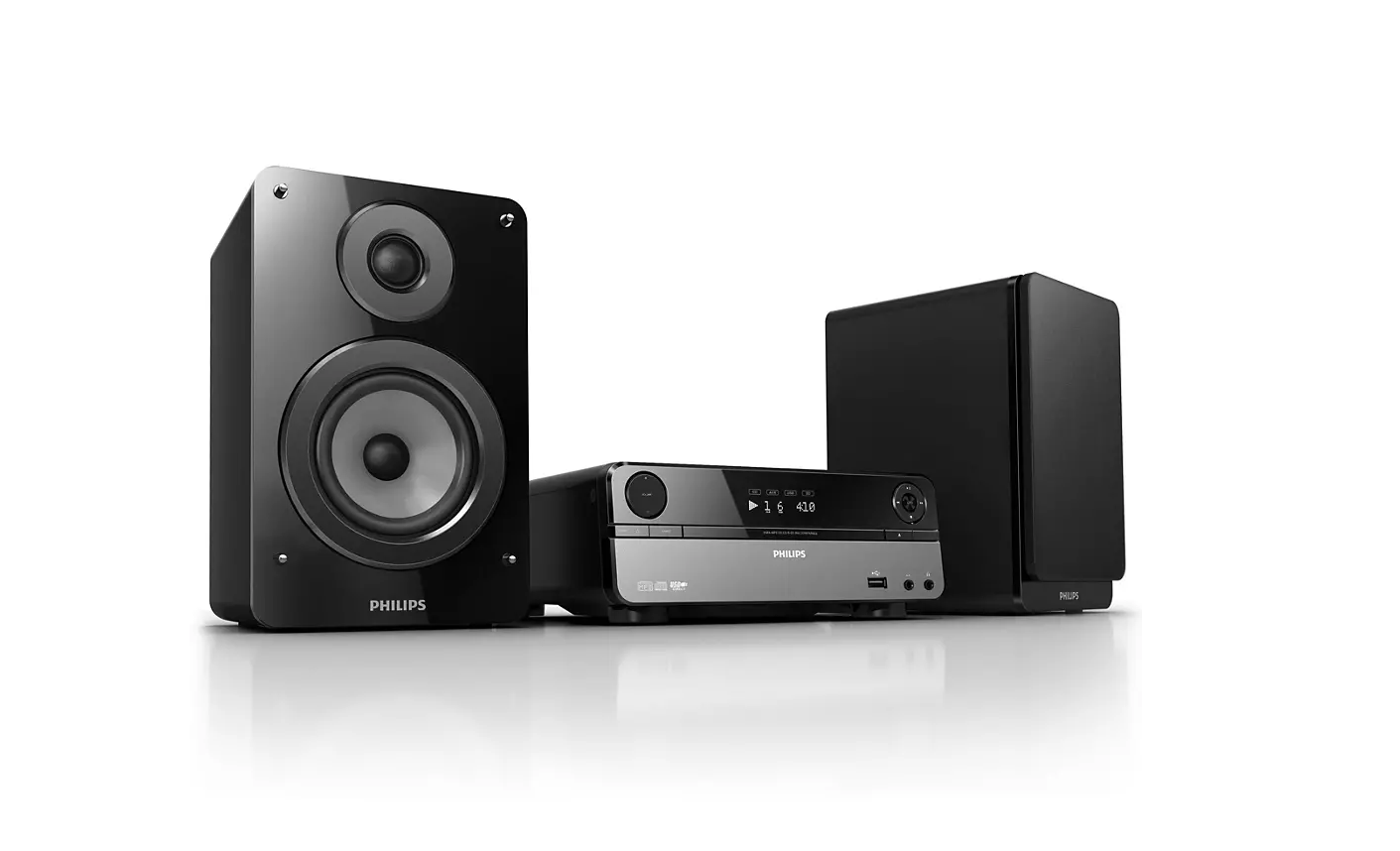
Music player hiding in a cooking pot. Project that has always been on my mind is now taking its first shape. Its internal organs were donored by an broken DVD player, from which I salvaged the power supply and the audio amplifying circuit.
Sometime ago I found this old DVD player and a set of speakers, which I used for listening to music, for years. If I turned off my laptop, which was connected to the AUX input of the DVD player, it would make this annoying sound. Can’t remember if it was high-pitched squeeching or a low-pitched hum, but anyways I ended up turning off the DVD player everytime as well. But for this, I would have to…STAND UP AND PRESS AN EXTRA BUTTON, so something had to be done about it.
My knowledge and motivation in audio electronics are not too great, so I decided to do a simple but good-enough hack: wireless control of the power button on the player. So, the first step was clear: open up the case, figure out what is going on, locate the power button, add a wirelessly-controlled-switch somewhere around there.
Aaand it’s gone
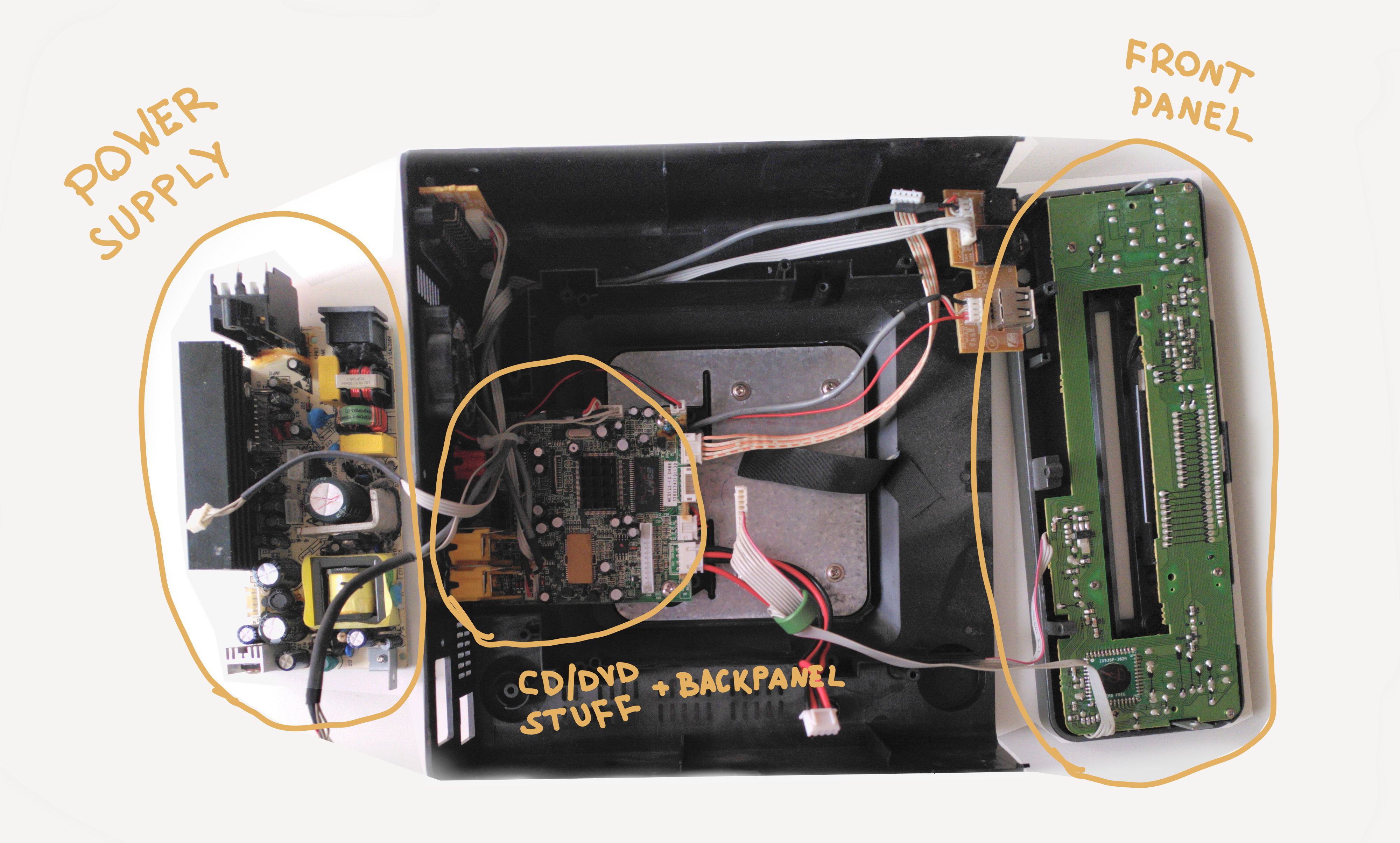
I managed to open the case of the DVD player (Phillips MCD 122) and guessed what the three PCBs are for: power-supply, CD/DVD stuff and the “frontend”.
Since the power button was located on the front panel, I focused on the “frontend” PCB only. It’s called the display board in the Phillips’ service manual which contains lots of schematics and was useful in figuring stuff out. Kind of.
There was an IC1 connected to all the buttons and the LCD display, with some wires going to other parts of the system (eg. power supply board). I soldered a wire to the input pin where the button was connected and tried applying different voltages to it: GND, 2.7V, 3V and 5V. Nothing seemed to do the job. In fact, after some more desperate poking around, the original buttons stopped working and the whole display didn’t turn on anymore. I fried the chip, I guess, whoopsie.
Well, it was fun anyway. In retrospect, I see that buttons are connected in somekind of a matrix which I’ve seen before somewhere, it’s probably a popular trick for saving GPIO pins and might explain why the button did not behave the way I expected. Anyways, better luck next time.
ZX935P; Can’t find much about it on the internet. Is it a microcontroller? An LCD driver? ↩
The DVD player, which I used as an audio amplifier, was now broken and I was left in silence. However, all the power and audio electronics were on a separate board altogether and were probably intact. What if I could just use that part of the circuit (instead of buying another amplifier) and give it a new home, a new housing, like a cooking pot. Because why not.
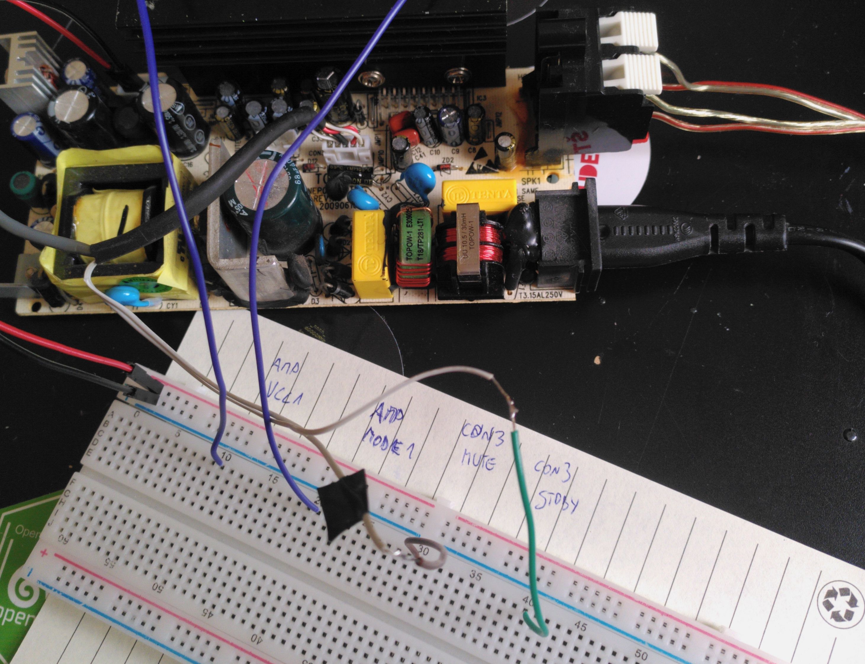
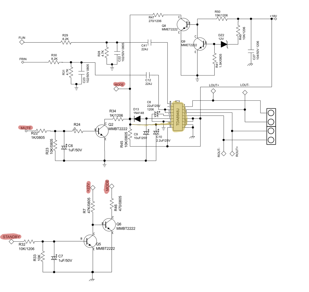
I found the audio amplifier IC (TDA8948J) and its datasheet which helped a lot in understanding the overall system and gave some meaning to the signal labels on the connectors.
Identifying the audio inputs and outputs was relatively easy, but I got confused with the modes of operation (STANDBY, MUTE, ON) which are controlled by applying a proper voltage on a specific pin (MODE1) of the TDA8948J. While I could not understand how this is implemented in the MCD122 (DVD player) circuit, simply applying the VCC voltage (+18 V) to the MODE1 pin worked! It is probably not the most elegant and sustainable solution, but at least there is a way of toggling between MUTE and ON.
With this, I had all the pieces ready to be put together into a pot and make it look pretty. Writing this post a year later, I noticed that htun85 answered my EE stackexchange question with a nice explanation. Wish I had this knowledge a year ago, before I put everything together. Oh well, at least I understand the circuit now :)
At this point, I had a disassembled DVD player and I knew the audio amplifier and its pinout. Also, voltages on the power pins looked okay.
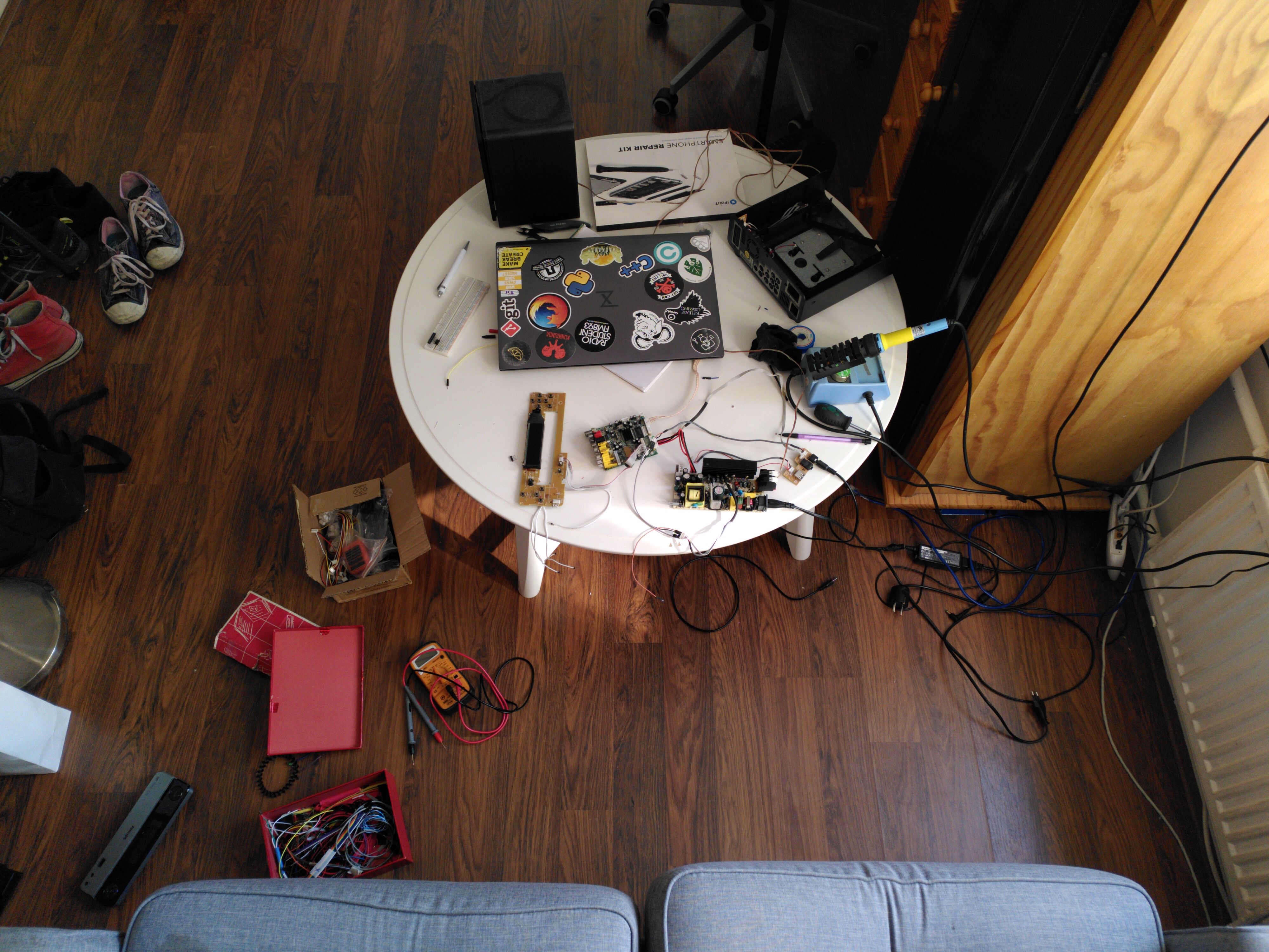
It was time to test it using my phone, an AUX cable and awkwardly holding three wires on the 3.5mm jack connector - but IT WORKED! The audio circuit is STILL ALIVE AND KICKIN’!
Also, the photo shows my super neat and professional work environment. I miss that room, it was a really cosy place :)
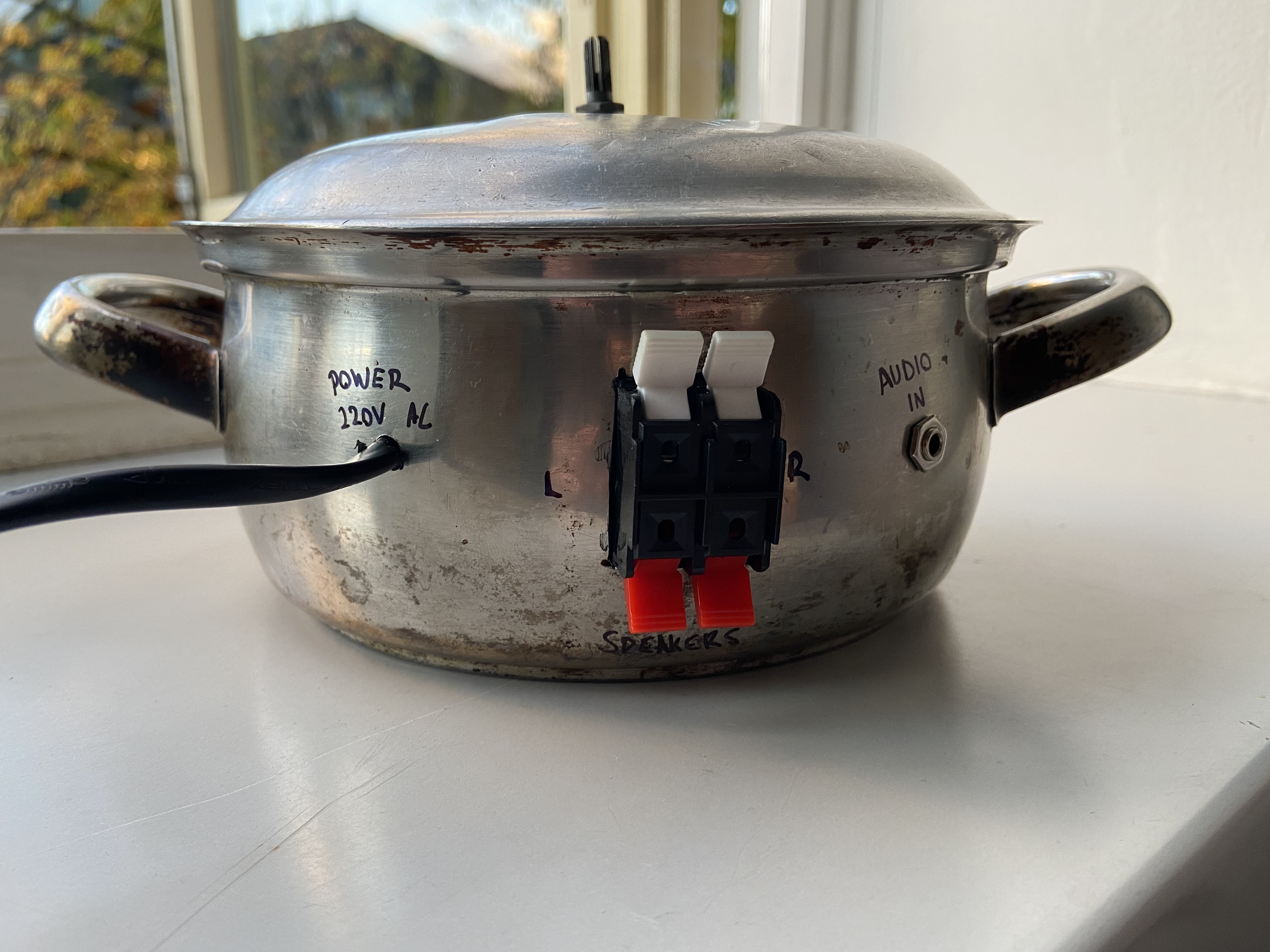
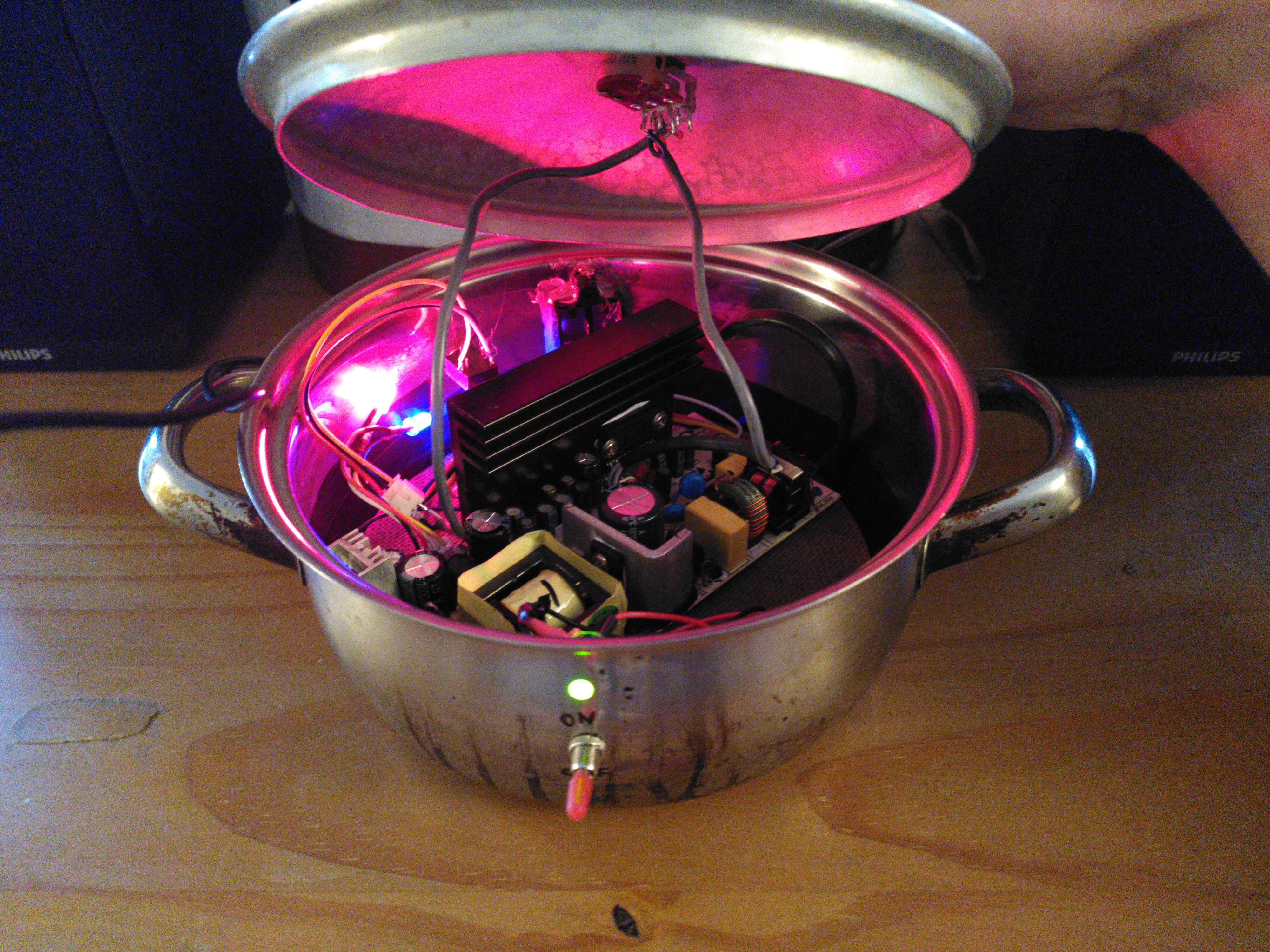
My favourite part of this project started here - putting everything together. Oh man, for a long time I had this idea of a random cooking pot sitting on my bookshelf and playing music, it had to be done.
There were some old pots sitting in our basement where we had somekind of a in-house second hand shop (free, old stuff). I choose one which was big enough to fit the PCB, drilled the holes for connectors, buttons and LEDs and…. eh, I’ll let the photos speak:
I probably already mentioned that I am not too confident in my electronics knowledge. One of the things I was worried about was having the 220V coming into my metal pot, which doesn’t sound safe. But since the power supply circuit came from a commercial DVD player and it seemed well protected I went with it. Added some isolation to prevent accitental contants and shorts - is this needed? What would be the safe and proper way to put such a thing in a metal pot? Educate me, please, I’ve got no electrical-engineering friends :)