Salvaging the audio amp
The DVD player, which I used as an audio amplifier, was now broken and I was left in silence. However, all the power and audio electronics were on a separate board altogether and were probably intact. What if I could just use that part of the circuit (instead of buying another amplifier) and give it a new home, a new housing, like a cooking pot. Because why not.
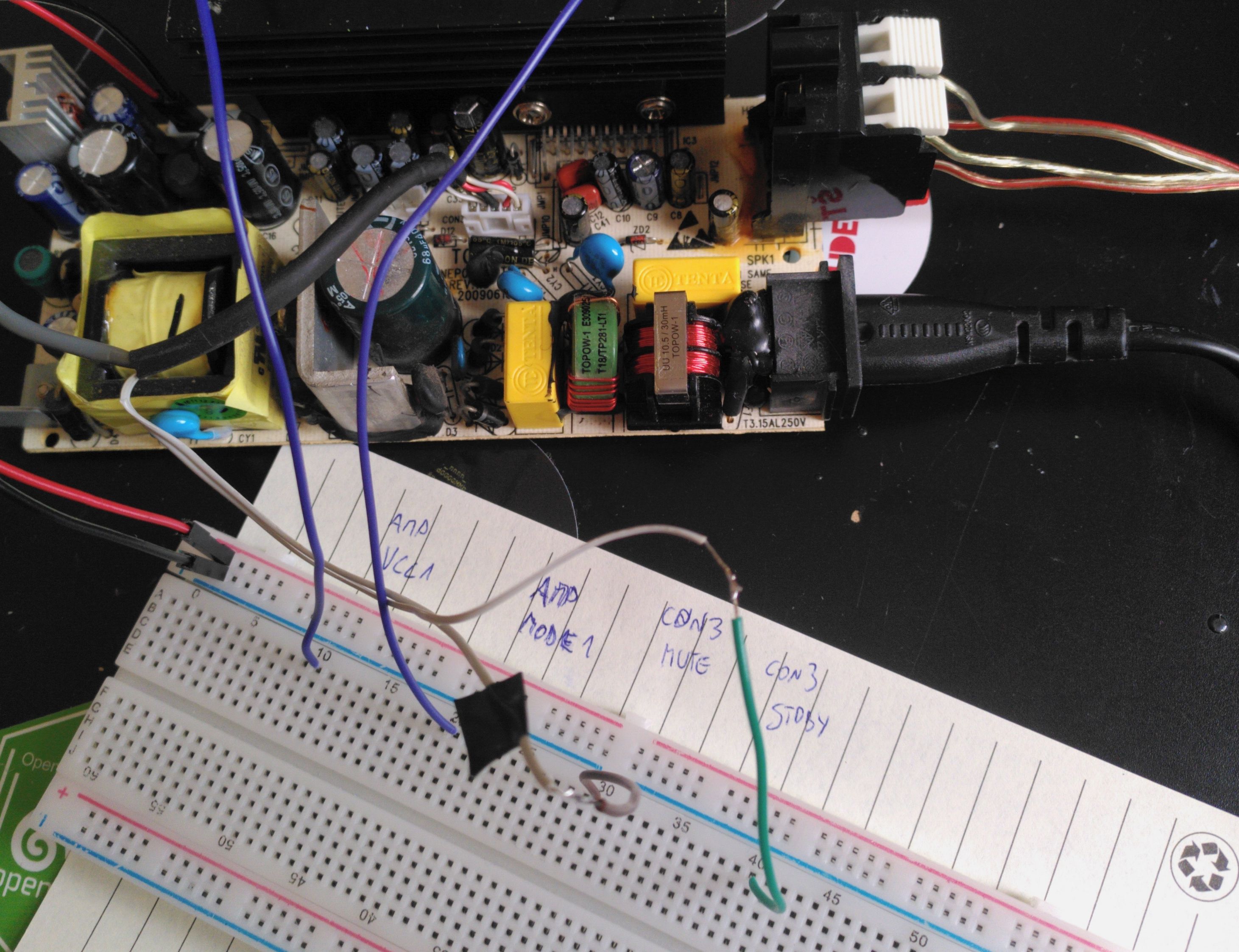
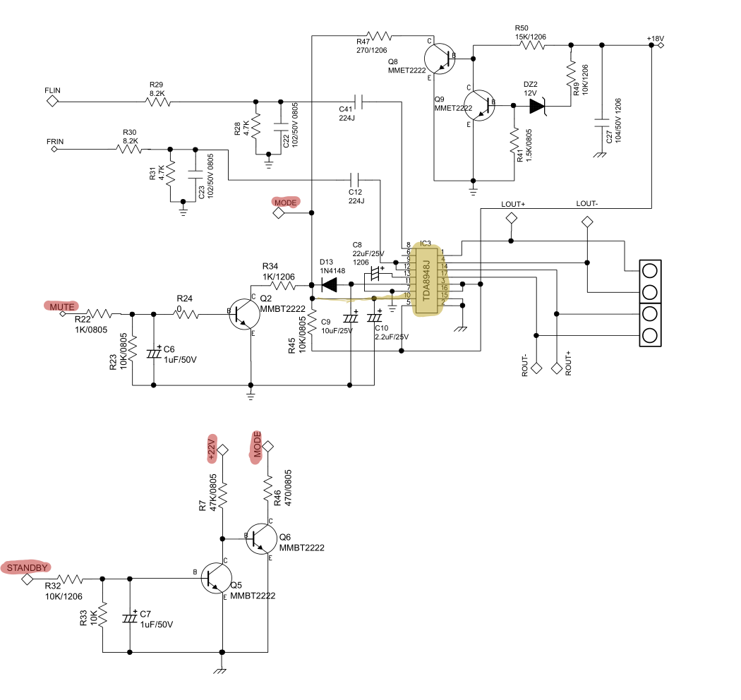
I found the audio amplifier IC (TDA8948J) and its datasheet which helped a lot in understanding the overall system and gave some meaning to the signal labels on the connectors.
Identifying the audio inputs and outputs was relatively easy, but I got confused with the modes of operation (STANDBY, MUTE, ON) which are controlled by applying a proper voltage on a specific pin (MODE1) of the TDA8948J. While I could not understand how this is implemented in the MCD122 (DVD player) circuit, simply applying the VCC voltage (+18 V) to the MODE1 pin worked! It is probably not the most elegant and sustainable solution, but at least there is a way of toggling between MUTE and ON.
With this, I had all the pieces ready to be put together into a pot and make it look pretty. Writing this post a year later, I noticed that htun85 answered my EE stackexchange question with a nice explanation. Wish I had this knowledge a year ago, before I put everything together. Oh well, at least I understand the circuit now :)